
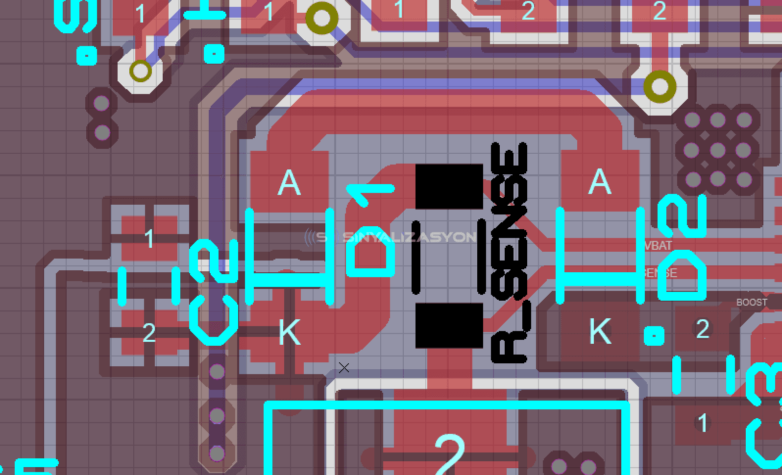
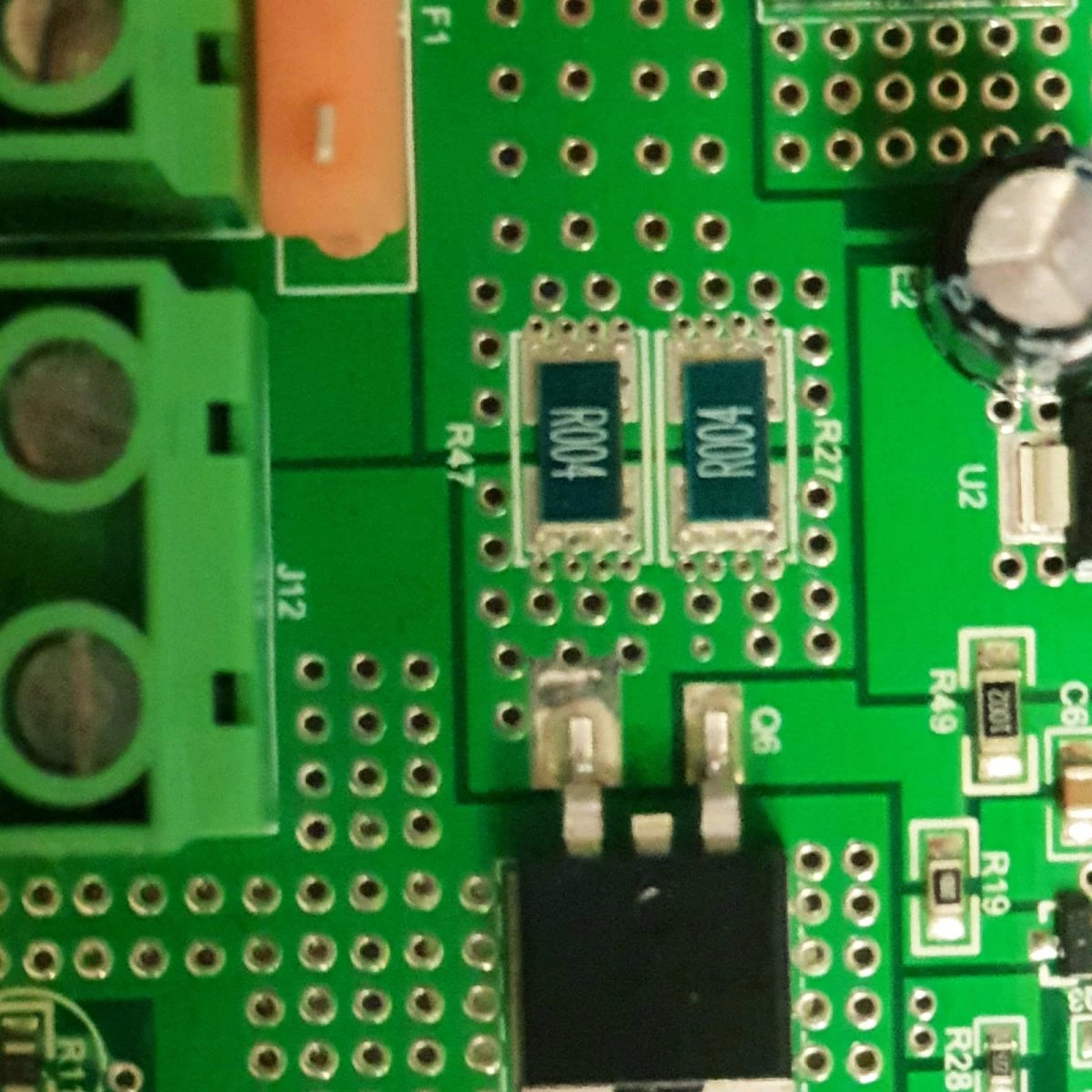
By Ohm's law, current flowing through a resistor produces a voltage across its terminals. In charge control systems, current is measured by placing near-zero-value resistors in series in the current path and measuring the voltage across them. Since the power dissipated equals the square of the current times the resistance, these very low values keep the power turned into heat very small. But because the resulting voltage (V = I × R) is only a few millivolts, the measurement becomes very sensitive to design errors. The Kelvin method sets out design criteria that keep this error to a minimum.
Kelvin sensing measures at a precise current or reference point in a way that removes the effect of contact resistance. It reads the small voltage across a sense resistor, typically 0.01–0.1 Ω, with lower values used for higher currents. The Kelvin sense lines must connect directly to the Rsense resistor, and in the layout they must be of equal length and width, and symmetrical. Any extra resistance from a layout mistake adds a voltage drop and produces wrong readings. In figures 1 and 2 below, A and B are the Rsense pads, and C and D are the Kelvin sense pin inputs.
Figure 1 shows an example of a correct layout.
Figure 2 shows an example of a faulty layout. When the sense lines are expected to read 100 mV, they also pick up the trace drop between A–X and B–Y, so they read more than 100 mV and the current reads higher than its true value.