
Proteus, used for electronic board design, has two sub-programs — ISIS and ARES — so that it can be used for both schematic design and printed circuit board design.
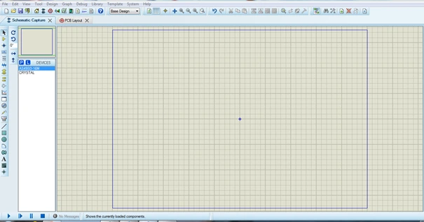
ISIS is the program in which the connections of the design and the general outline of the system are laid out visually, as a schematic.
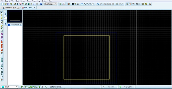
ARES is the program that helps us turn the board we designed schematically in ISIS into a full-size printed circuit, joining the components with pads and traces. When drawing in ARES we can use traces for connections, and we can also use one of the pad types, which divide broadly into Through-Hole (DIP parts) and SMT (SMD parts).
SMT pads divide by purpose into four: Edge Connector Pad Mode, Circular SMT Pad Mode, Rectangular SMT Pad Mode and Polygonal SMT Pad Mode. The polygonal pad is used where several pins share a common connection, or where a special concave or convex polygon shape is needed.
Drawing a Polygonal Pad
1. When creating the new pad shape, the 2D graphic line, Arc or Path icons are used, whichever suits the purpose.
2. Place an Origin Marker at the centre to define the centre of the pad you have drawn.
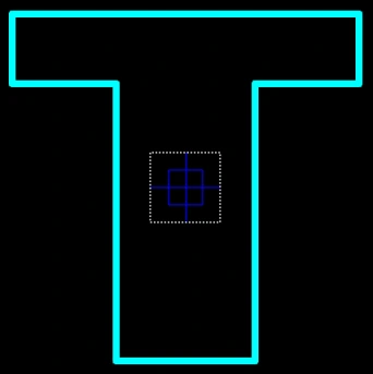
3. Hold down the right mouse button and drag a selection enclosing both the pad you drew and the Origin Marker.
4. From Library, choose New Pad Style.
5. Enter a name for the new pad.
6. For the polygonal pad type, select Polygonal beneath SMT.
7. Click OK.
8. If the pad you have created needs a clearance, specify a Guard Gap for the pad style.
9. Choose LOCAL EDIT if you want the resulting pad only in the current project, or UPDATE DEFAULTS if you want it available in your other projects too.
10. Click OK to create the new pad.