
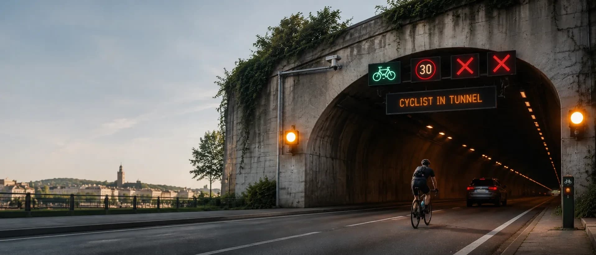
Tunnel cyclist warning system with camera detection
TBUS warns drivers by detecting a cyclist at the tunnel entrance from the camera image. It manages the warning process according to the entry and exit detections, and gives the tunnel operator local control and central monitoring.
What is TBUS?
TBUS is a tunnel cyclist warning system that detects a cyclist at the tunnel entrance from the camera image using artificial intelligence, and starts the defined warning scenario to warn drivers.
Entry and exit cameras, a PoE network switch inside the panel, two independent warning outputs, an external field button and the local panel display work together; image processing and warning control run on site. The detection method and the devices the warning outputs drive are chosen per project.
- Supply
- 220 V AC, 50 Hz
- Camera power
- PoE from the switch inside the panel
- Warning outputs
- 2 independent channels
- Button input
- External field button
- Communication
- Ethernet / Modbus TCP
- Climate control
- Fan and heater
How the tunnel cyclist warning system works
- Detection — The defined area in the camera image is analysed by artificial intelligence for bicycle detection.
- Verification — The continuity of the detection and object tracking are evaluated, and a cyclist demand is created.
- Warning — The warning outputs are activated according to the set duration and operating mode.
- Termination — The exit detections are evaluated; the warning ends when the active demand is over or the set timeout expires.
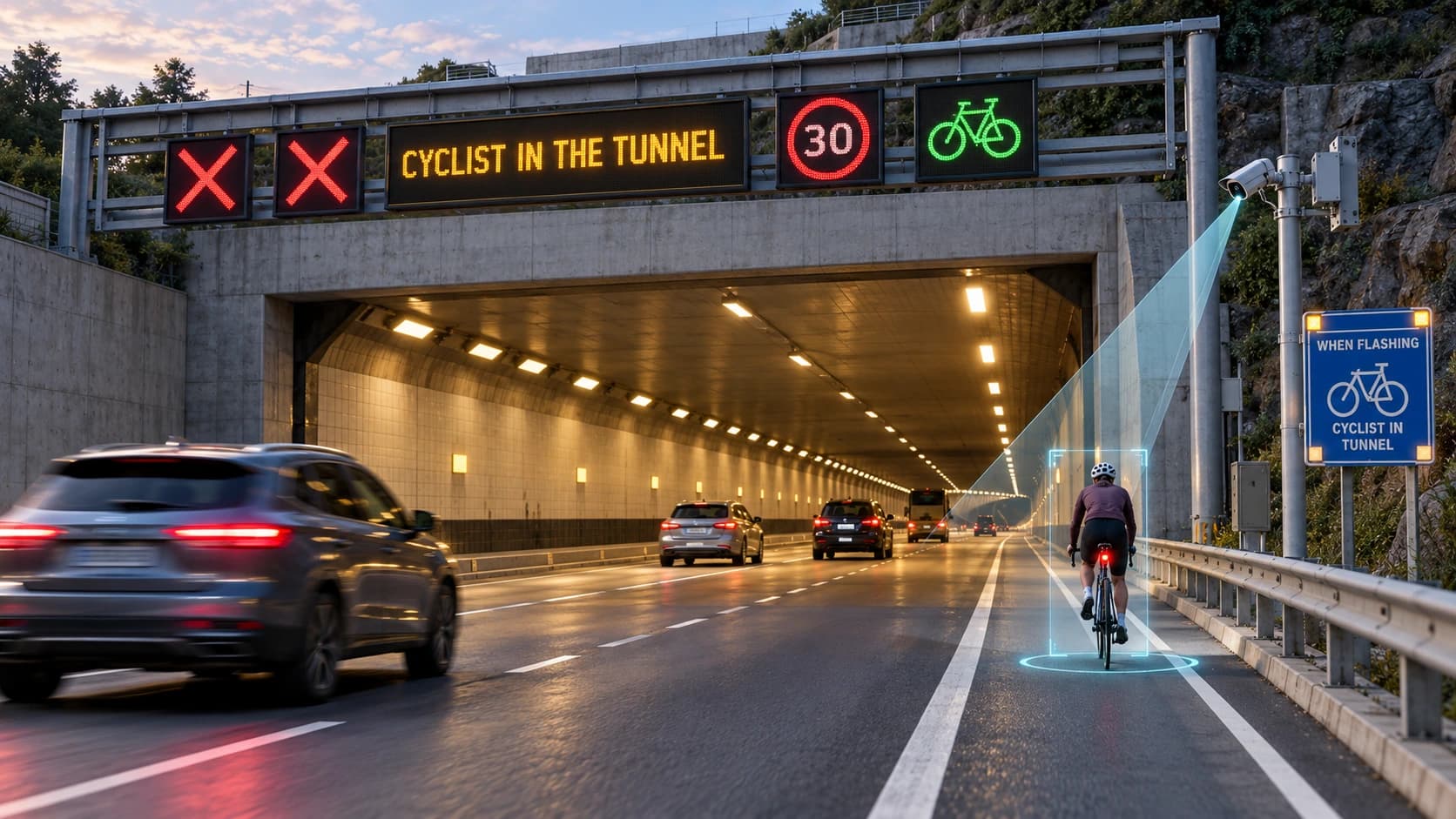
Detection methods and warning devices
The detection method and the warning devices are chosen per project.
Detection
- Artificial intelligence analysis of a defined area in the camera image
- Radar
- External field button
Warning devices
- Flashing warning lamps driven from the two independent channels
- Variable speed limit signs
- Lane control signs
What can be set on site
- Detection zone
- Warning durations
- Output behaviour per channel
- Flash duration per channel
- Warning delay
- Demand timeout
- System operating mode
Control and operation
Local monitoring
The cyclist demand, the entry and exit counters, the camera status and the fault information can be monitored from the panel display.
Adjustable warning
The operating form and flash durations of the two independent outputs are set separately. The warning delay and the demand timeout are set per site.
Operator control
In addition to camera detection, a demand can be raised with the field button. The operating mode can be selected and an active demand can be ended from the local display.
Maintenance information
The communication status, temperature and electrical measurements are shown on the local display.
Local operation
Image processing and warning control run on site. The entry and exit cameras are evaluated together; camera placement and warning points are planned according to the structure of the tunnel.
SCADA integration over Modbus TCP
The cyclist demand state can be passed to the SCADA system over Modbus TCP. The operating mode and the warning durations can be set remotely, and commands can be given to raise a demand and to end an active demand.
Specifications
- Supply voltage
- 220 V AC
- Mains frequency
- 50 Hz
- Camera power
- PoE from the switch inside the panel
- Warning outputs
- 2 independent channels
- Button input
- Triggered by an external field button
- Communication
- Ethernet / Modbus TCP
- Electrical protection
- Supply and output fuses; earth-leakage protection
- Climate control
- Fan and heater
What a TBUS installation is built from
Detection cameras
Cameras positioned at the tunnel entrance and exit, powered over PoE from the network switch in the panel.
Network switch
The switch inside the panel that powers the cameras over PoE.
Warning outputs
Two independent channels; depending on the project they drive flashing warning lamps, variable speed limit signs or lane control signs.
Field button
An external button that raises a cyclist demand alongside camera detection.
Control panel
Holds the network switch, the supply and output fuses, the earth-leakage protection, the fan and heater and the local display.
Frequently asked questions about tunnel cyclist warning
How does TBUS detect a cyclist?
The defined area in the camera image is analysed by artificial intelligence; the continuity of the detection and object tracking are evaluated, and a demand is created.
Does TBUS work with radar?
Yes. Standard detection is from the camera image; radar and an external field button are also used, chosen per project.
Can TBUS drive speed and lane signs?
Yes. The two independent warning channels drive flashing warning lamps, variable speed limit signs or lane control signs, depending on the project.
How many warning outputs does TBUS drive?
Two independent channels. The behaviour and flash duration of each channel are set separately.
When does the TBUS warning end?
The exit detections are evaluated; when the active demand is over, or when the set timeout expires.
Can TBUS connect to a SCADA system?
Yes, over Modbus TCP. The demand state is passed on, and the operating mode and warning durations can be set remotely.
Does TBUS work without a connection to the centre?
Yes. Image processing and warning control run on site.
Integration with the tunnel operator
Detection and warning control run in the tunnel, on site; no central system is required. Where the tunnel operator runs a SCADA system, TBUS connects to it over Modbus TCP.
Related solutions
Contact us about tunnel cyclist warning
Send the tunnel length, the entrance and exit layout and the SCADA system in use.