
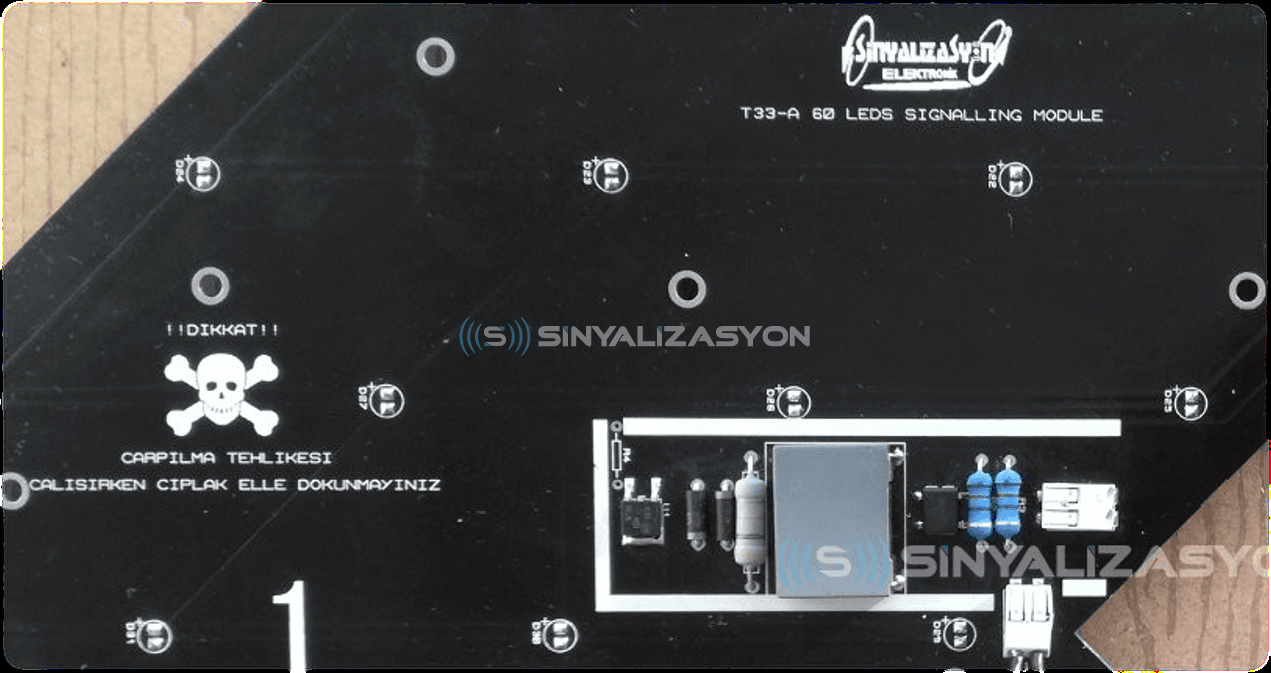
There are several ways to convert an AC voltage into the DC level a microcontroller or an LED matrix needs. Traditionally, a step-down transformer and a rectifier are used: a sufficiently large capacitor at the rectifier output smooths the signal towards DC, and a driver circuit then regulates that DC for the output. A ready-made SMPS (switch-mode power supply) is another option. Neither is necessarily cost-effective. At low power, transformers now often cost more than an SMPS of the same rating, and where the surrounding components cost far less than the power supply, a cheaper solution becomes necessary. In this article we describe a transformerless conversion technique with a power factor of 0.5 and low THD.
Transformerless dropper techniques come in two basic types: resistive and capacitive. The only advantage of the resistive dropper over the capacitive one is cost, and the difference is small enough to ignore, so we continue with the capacitive technique.
Important: capacitive and resistive droppers provide no isolation. Such designs cannot be connected in parallel or in series, and cannot be used where isolation is required.
The idea behind both the full-wave and half-wave rectifier versions of this circuit is that the line capacitor C1 behaves like a lossless resistor, and its reactance acts as a regulator that sets the maximum current available to the DC-DC input. Because C1 shifts the input current out of phase with the voltage, the power factor tends towards zero. A resistor of around 500 kΩ is connected in parallel with C1 to discharge it when the circuit is switched off. The lower this resistor's value, the more it heats up, so its value must be chosen with care.
When there is no load on the output side, the zener diodes clamp the rectified voltage at the zener level and so form a DC voltage source. The clamp voltage (the sum of the zeners) must be higher than the voltage the load needs. Suppose, for example, that we are driving a string of 8 red LEDs in series.
Clamp voltage = 8 × 2.1 V + regulator dropout = 16.8 V + ~3 V
Clamp voltage = 19.8 V
On the load side, a constant-current or DC/DC regulator can bring the unregulated DC voltage to the required level. The related calculations are available at
http://www.ti.com/lit/an/snva735/snva735.pdf
(Texas Instruments application note SNVA735).